

Making DNA in Grasshopper, Rhino
18th August 2021
For my first blog post, I thought I’d write about how I typically tackle writing a Grasshopper definition from scratch - I’m definitely no expert so by all means leave tips down below!
Anyway, making DNA.
18th August 2021
For my first blog post, I thought I’d write about how I typically tackle writing a Grasshopper definition from scratch - I’m definitely no expert so by all means leave tips down below!
Anyway, making DNA.
To make things easy for ourselves, let’s say for now we just want to turn a straight line into some DNA - simple enough, we define a point and use the line SDL component to create a straight line. Nice!
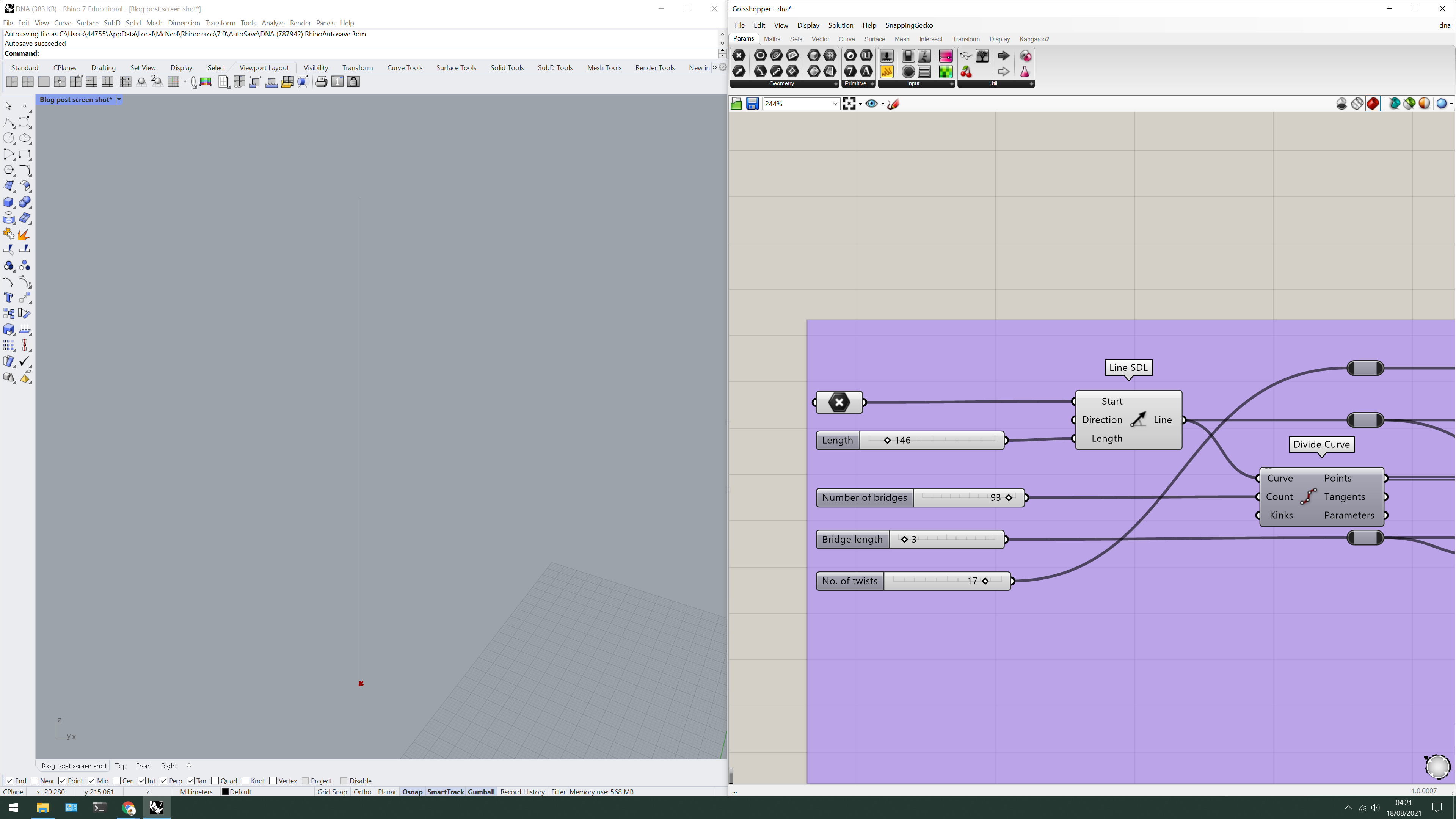
Create a straight line using the line SDL component
Okay, so, we have our straight line - or axis - so where do we begin with the actual DNA a.k.a the double helix?
The keyword here is double so we’re going to need two lines relative to the axis.
To do this, we can use the offset curve component - because we want the axis to remain central, multiply a single number parameter by -1 rather than connecting two separate parameters.
Now that we’ve got our two backbones which will form the double helix, it’s a good time to start thinking about the bridges that will connect them.
Instead of attaching a divide curve component to both curves (D.R.Y - don’t repeat yourself) I instead attached it to the axis and used the curve closest point component to project these points onto the two backbones.

Create two curves relative to the axis using the offset curve component
Create a list of points which will be used to form the bridges using divide curve and curve closest point
To get these backbones twisting to form the double helix, we simply use the twist component and supply the angle with a value of π - we can multiply this by any number we want to increase the amount of twists in the double helix.
Finally starting to look like DNA? No??
Finally starting to look like DNA? No??
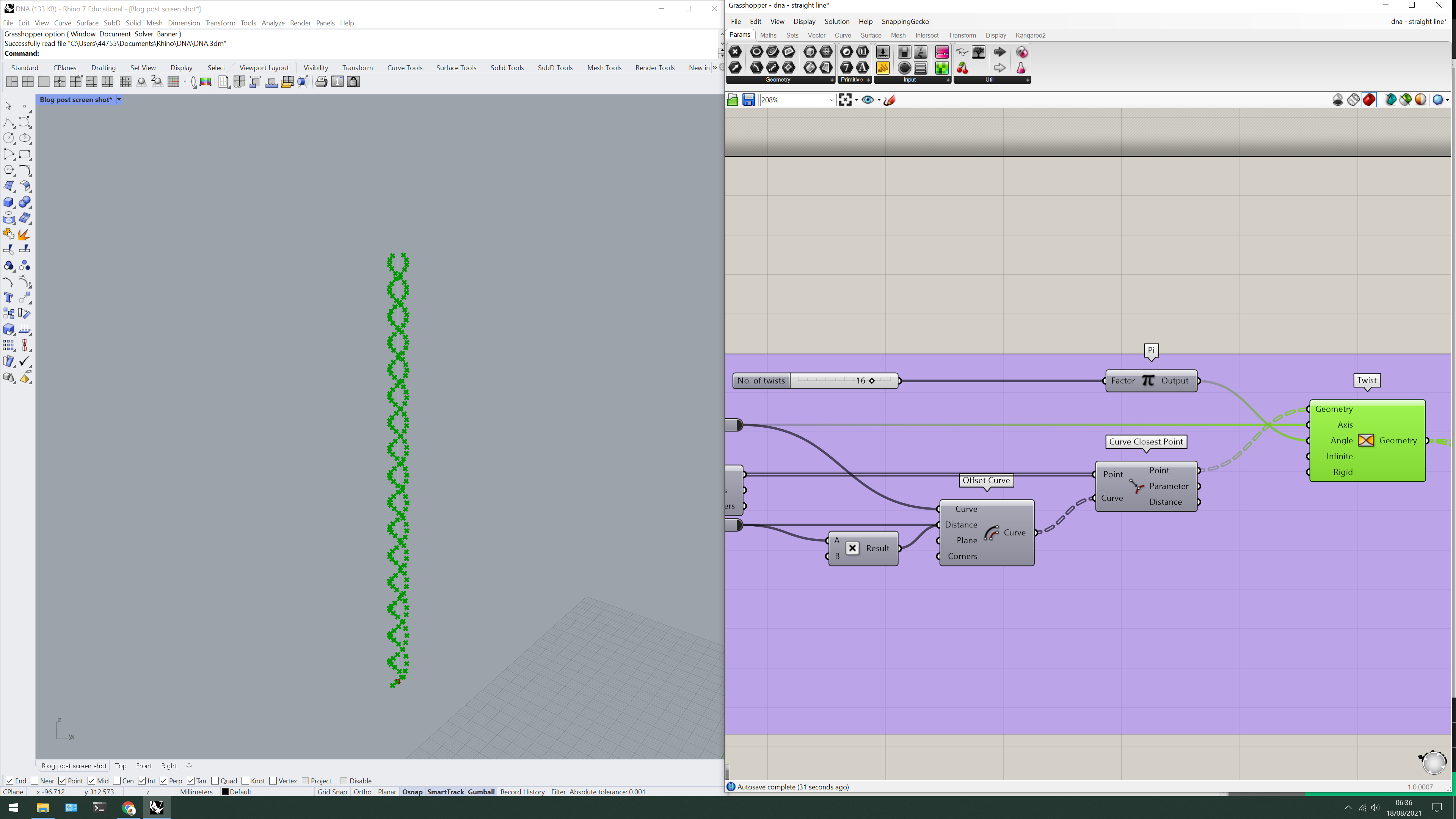
Use the twist component to twist the points forming the backbones
Start connecting all the points using the interpolate component for the backbones.
For the bridges, it’s a little bit trickier...
If you try and connect the start and end points using the shift list component and the line component, the lines will try to connect one point to the next along the same backbone giving us an undesired result. To fix this, we need to alter the data structure of the points so that they are paired differently - we can do this by inserting the flip matrix component before trying to connect the points.
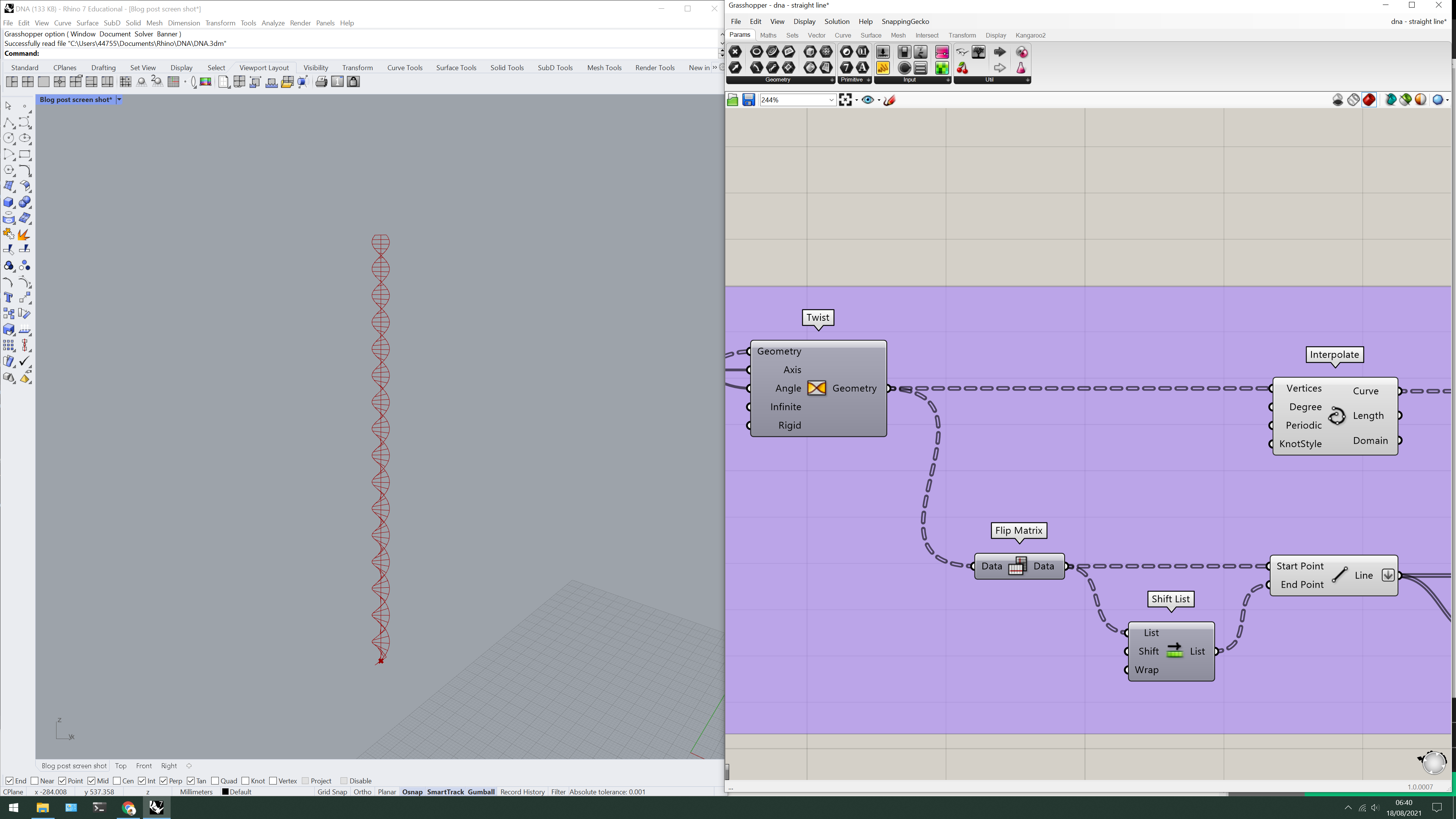
To create the backbone curves, use the interpolate component
Use flip matrix on the points to alter the data structure such that the points are paired the way we want them
Shift the list to move from one pair to the next using the shift list component
Use the line component to form the bridges
We could call it a day here but something inside me is screaming to get rid of the first and last bridge to get that classic DNA look - but how do we do this?
Why, using the cull index component of course!
We could enter the indices for this specific arrangement, but to make the DNA truly parametric, let’s take the list length component and subtract 2 to cull the last bridge and then just attach a panel containing the number 0 to cull the first bridge.
Pipe it all up using the pipe component and there you have it, a strand of parametric DNA. Amazing.
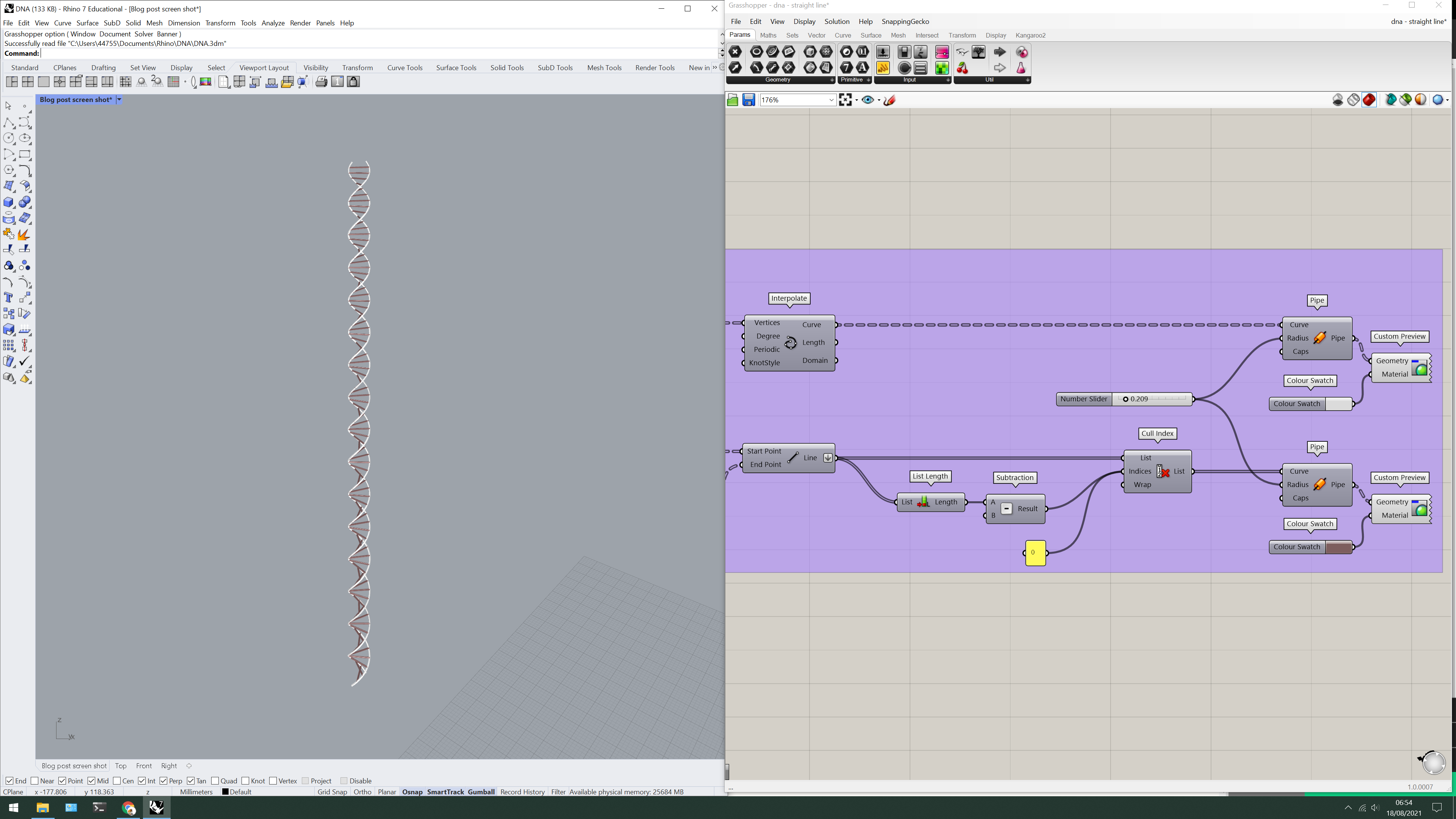 Subtract 2 from the list length component and insert it into the cull index component to cull the last bridge
Supply the number 0 using a panel to cull the first bridge
Pipe all curves using the pipe component